How Do You Build a Robot from scratch with a micro:bit?
Building a robot with the Micro:bit shows how accessible physical computing can be. With a few parts and simple code, abstract logic turns into real movement.

We've discussed how exploring code through hardware transforms abstract logic into something visible and concrete. After examining how the BBC micro:bit makes programming tangible, this project puts that idea into practice. The objective was straightforward: to build a fully functional robot from individual components rather than a prepackaged kit, using the Micro:bit as the control system. With only a few affordable parts, some 3D-printed mounts, and basic tools, it was possible to create a robot that moves under radio control and serves as a foundation for further experimentation.
In the sections that follow, we explore how the robot was designed, assembled, and programmed, illustrating the Micro:bit’s potential as an educational platform for physical computing.
Designing the Robot
The goal was to build a simple yet functional robot that demonstrated how the Micro:bit could serve as the foundation for physical computing projects. The challenge was to start entirely from scratch, using easily obtainable parts and minimal custom electronics. The final design drew inspiration from the common three-wheel configuration used in many beginner robotics kits, combining two powered wheels for movement and a third caster for balance. Unlike commercial robot platforms, this project would not rely on a pre-cut chassis or proprietary brackets. Instead, the components would be mounted on a small wooden board, creating a design that could be replicated in any classroom or workshop.
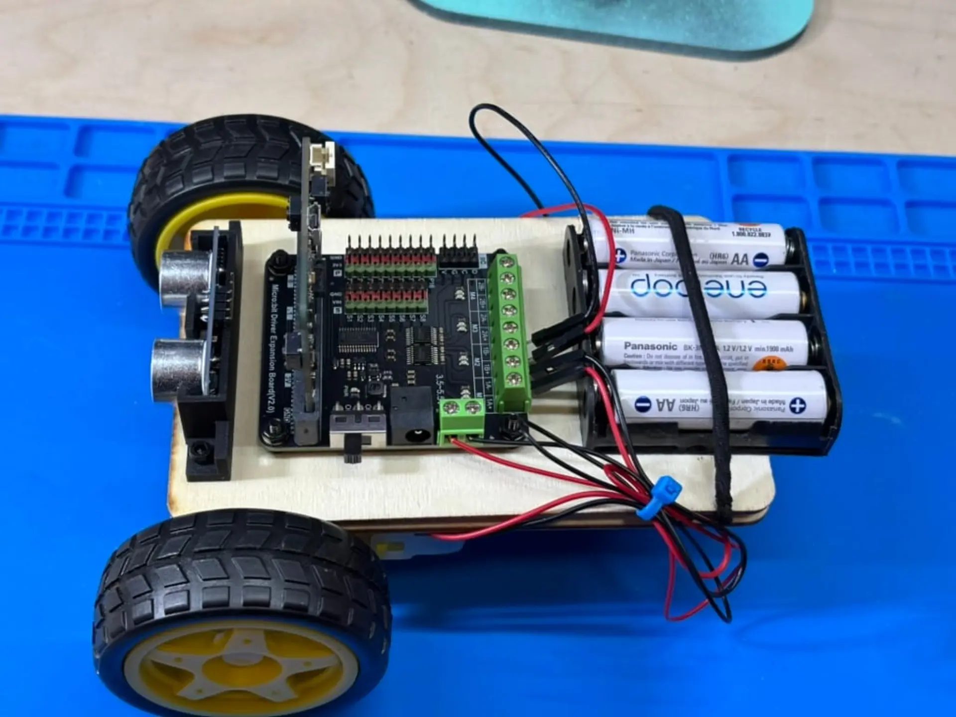
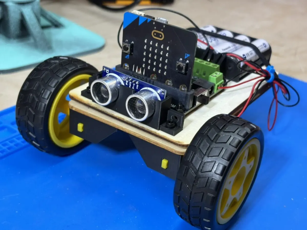
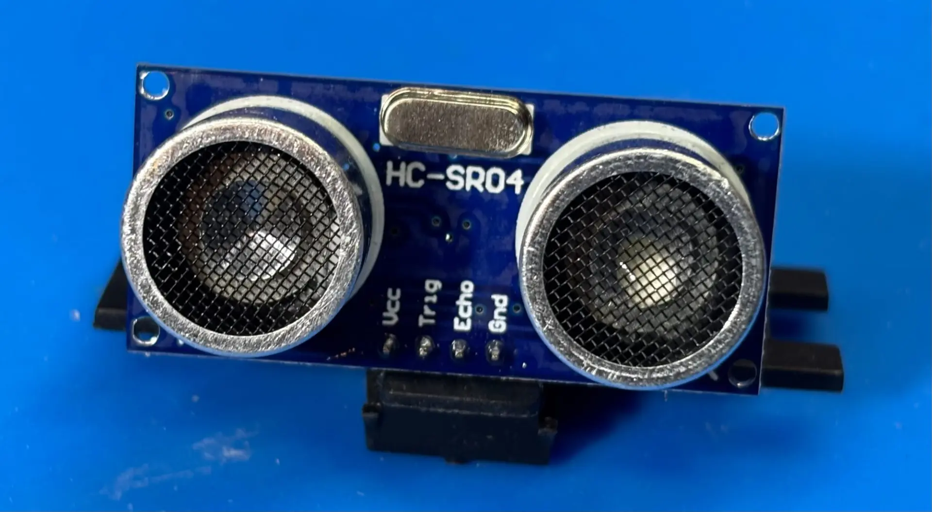
At the center of the system is the BBC Micro:bit v2, paired with a DFRobot DFR0548 motor driver expansion board. This shield allows the Micro:bit to control two TT gear motors through simple block-based code while drawing power from a shared battery pack. Although the DFR0548 is designed for 3 AA cells, it is rated up to 5.5 volts, allowing the use of four NiMH batteries that deliver roughly 5.29 volts when fully charged. This configuration provided stable power without exceeding the board’s limits. The two TT gear motors drive 65 mm rubber wheels, offering sufficient torque for the wooden chassis. An HC-SR04 ultrasonic distance sensor was also included in the parts list, though it was postponed for a future upgrade due to its 5-volt signal output, which the Micro:bit cannot safely handle without level shifting.
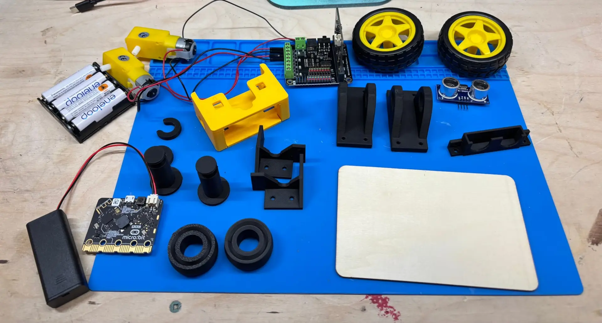
To simplify assembly, all structural elements were sourced from open designs on MakerWorld. Printed parts included motor mounts for the TT motors, a 40 mm caster for balance, M2 and M3 spacers to elevate the motor board above the chassis, and a dedicated bracket for the ultrasonic sensor. Using existing 3D models saved significant time while showcasing the advantage of open-source fabrication resources.
Building the Chassis
Before cutting or drilling, the project began with a proof of concept. The two Micro: bits were paired wirelessly to confirm that one could act as a remote control and the other as the robot’s brain. Once the motors responded to commands, construction moved forward with confidence that the control logic would function once the hardware was assembled.
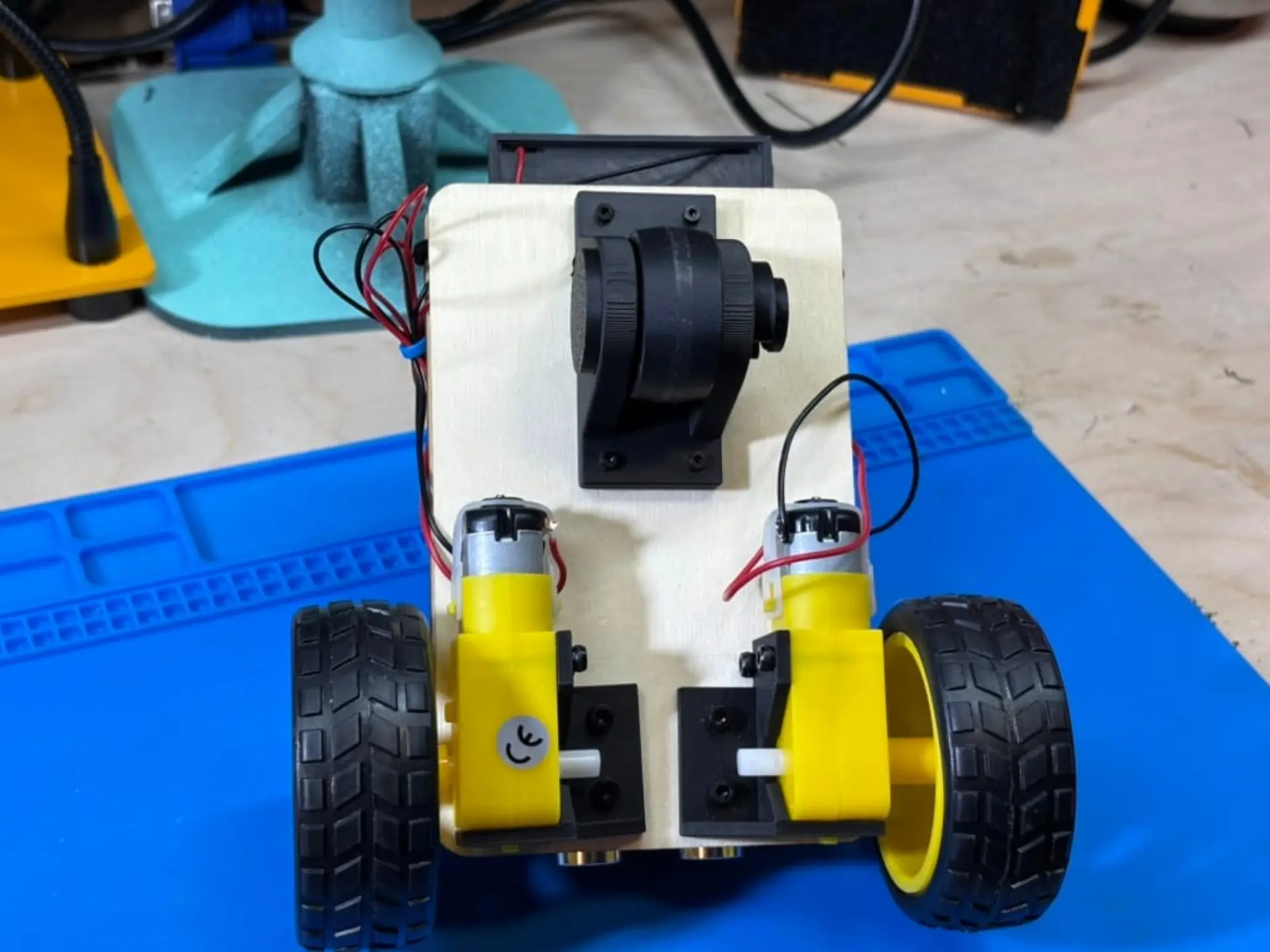
Both top and bottom chassis were built from a 14 by 9 centimeter wooden craft board, chosen for its simplicity and availability. Components were mounted using a combination of M2 and M3 screws, with spacers ensuring that the electronics never made direct contact with the wood. The TT motors were attached to the bottom chassis first using 3D-printed brackets, giving the robot its primary structure and defining the placement of all other components. Because of the motor mount geometry, one of the TT motors had to be installed upside down. This created a small but important quirk: to move the robot forward, one motor must spin clockwise while the other turns counterclockwise. A 40 mm 3D-printed caster wheel was mounted toward the rear, completing the three-point support system and allowing smooth movement in any direction. The wheels were fitted onto the TT motors and tested for clearance before any wiring began.
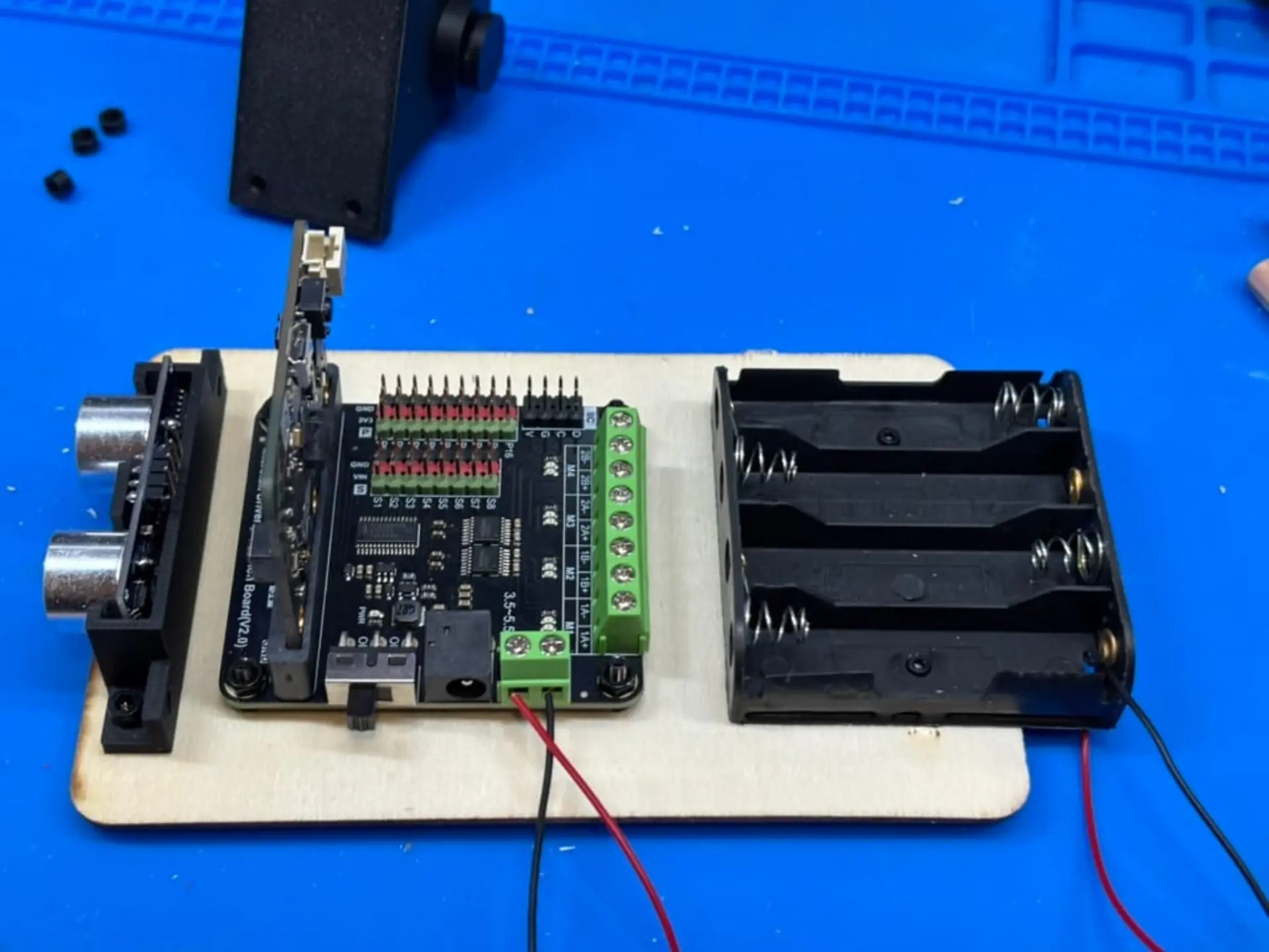
Because of the placement of components, a top board with the motor driver, Micro:bit, ultrasonic sensor, and battery pack was added to create a two-tier design. The two layers were joined with Velcro, an approach that simplified maintenance and allowed for quick access to the wiring underneath. Once assembled, the batteries had a tendency to pop out of their sockets. An elastic was added to hold down the batteries firmly in place.
Programming and Debugging
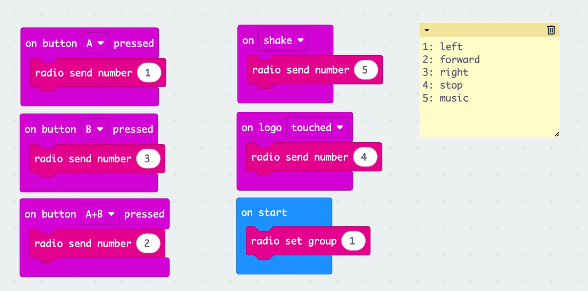
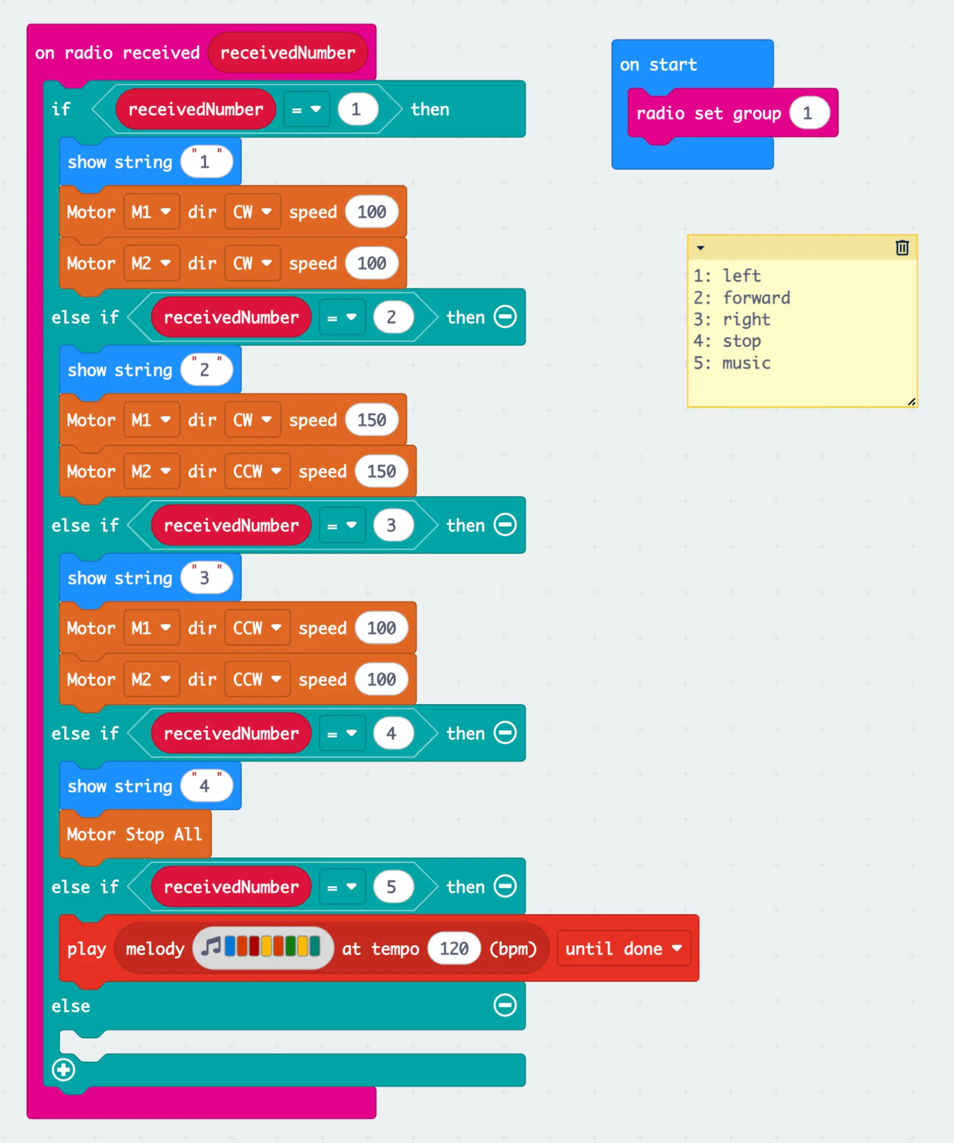
With the physical chassis complete, the next step was to bring the robot to life. The control system used two Micro:bit v2 boards communicating wirelessly through the built-in 2.4 GHz radio. One Micro:bit acted as the controller, sending movement commands as simple integer messages, while the other interpreted these signals and drove the motors through the DFR0548 expansion board. The control scheme was straightforward: 1 for left, 2 for forward, 3 for right, 4 for stop, and 5 for sound. Using small numeric codes kept the logic compact and easy to troubleshoot. The code was written in Microsoft MakeCode, allowing quick iteration and real-time testing.
Early experiments focused on refining movement control. The first version of the code powered only one motor during turns while leaving the other idle, which resulted in wide, uneven curves. Adjusting the logic so that one motor spun forward while the other turned in the opposite direction produced tight, controlled rotations. This change also revealed the earlier hardware quirk. Because one motor was mounted upside down, its wiring had to be reversed for forward motion. Correcting this in code ensured that both wheels rotated in sync when the robot advanced.
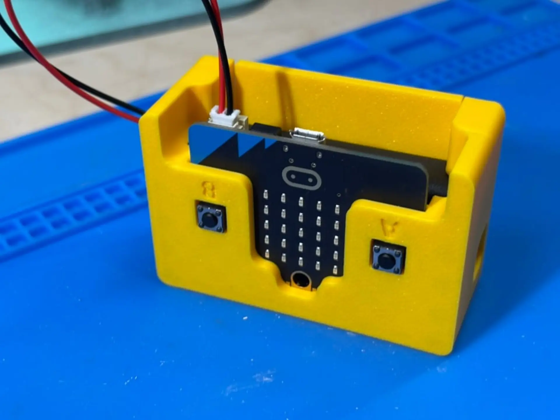
Programming the controller introduced its own set of limitations. The Micro:bit’s two push buttons and single capacitive logo provided only three input options, enough for basic navigation but restrictive for smooth driving. The radio connection worked reliably, but its latency was noticeable, requiring some practice to steer accurately. Even with these limits, the system proved functional and responsive enough for experimentation. The ultrasonic sensor was intentionally left disconnected during this phase. Because it operates on a 5-volt signal, connecting it directly could damage the Micro:bit’s 3.3-volt input pins. A voltage divider or logic-level converter will be required before it can be safely integrated in a future version.
Future Upgrades
With a working foundation established, the next phase will focus on refinement rather than reconstruction. The most immediate improvement will be upgrading the controller. The current three-button configuration limits precision, making it difficult to manage gradual turns or variable speeds. Replacing the second Micro:bit with a dedicated joystick module, such as the ElecFreaks Joystick:bit V2, would introduce analog input for smoother directional control and proportional speed adjustment. This enhancement would transform the robot from a simple proof of concept into a more capable driving platform.
The second major upgrade involves integrating the ultrasonic distance sensor. Once a voltage divider or logic-level converter is added, the HC-SR04 can safely connect to the Micro:bit’s 3.3-volt input pins. This will enable autonomous behaviors such as collision avoidance or distance-based stopping, expanding the robot’s educational value. The modular design of the current chassis leaves ample room for additional wiring and sensors, simplifying this future addition.
Finally, the wooden prototype will eventually be replaced with a fully 3D-printed frame. A printed chassis would allow tighter integration of mounting points, better alignment of components, and improved balance. Each of these upgrades continues the same principle that guided the initial build: creating an open, affordable, and tangible way to understand how code translates into motion.
It's a Robot
The Micro:bit can absolutely serve as the foundation for building a robot, but this is only the beginning of the journey. Creating a mobile platform requires little more than a pair of motors, a driver board, a set of wheels, and a sturdy base to bring it all together. The real value lies not in the hardware itself, but in what it teaches. Each iteration, each adjustment to code, balance, or wiring, turns experimentation into understanding. Robotics is less about building machines and more about discovering how ideas move when given form.
Have you ever built a robot? Whether it rolled, walked, or simply blinked an LED, every build reveals something new about how code shapes motion. Share your favorite robotics projects or lessons learned in the comments below. If you enjoyed this exploration of DIY robotics, you might also like our coverage of the CrunchLabs Domino Robot, a hands-on builds that combine engineering and play to make coding tangible.


